   |


This is the engine mount, not the outer airframe.
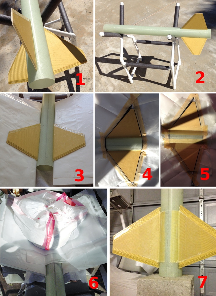
1 & 2 are simply pictures of the fins, before applying tip-to-tip.
Tip-to-tip is a technique of applying layers of fiberglass to a near-minimum diameter rocket. This gives the rocket strength, since there can't be reinforcement within the airframe.
In my case, my rocket is near minimum diameter - outer airframe is 4.38 inches in diameter with a 4.01 inch diameter engine mount. I have the luxury of applying this technique on the engine mount, rather than the outer airframe. Thank you Tony McCrea for suggesting this technique to me.
My plan is to do a form of vacuum bagging. Instead of using a vacuum system (very hard on such a large object), I am going to apply 50 pounds of sand to the top of the fin can, distributing the weight evenly with the odd shape of the two fins that will be tip to tipped per epoxy lamination. Vacuum bagging is a technique where you apply a peel ply (a membrane that epoxy can pass through) on your surface, followed by an absorbing layer (such as a cottony fabric). This allows excess epoxy to be bled away from your lamination, making your entire object pressed tight and strong with no excess epoxy. When done, you struggle and peel the peel ply layer off, and are left with a beautiful finished surface.
Image 3 shows the form jig with the fins and engine mount installed. I created a make shift jig out of cinder blocks, chairs, wood, and two formica planks. The engine mount rests on the chairs, and is cradled in place with weights to either side. Then, I used bricks and cinder blocks to support the two formica planks. These are firmly supporting the fins, flat up against them. Since I have 50 pounds of sand I am laying on top, I didn't want any chance of even slight warping of the fins.
In image 4, you can see where I taped the area that I wanted the glass to be contained in. I used electrical tape, and then masked sheets of plastic onto the electrical tape for overrun on the fiberglass.
I then applied one layer of 5 oz kevlar, one layer of 5oz fiberglass(larger), and one sheet of 2oz fiberglass covering the entire taped off area. Image 5 shows this completed.
I placed peel ply on top of the entire exposed laminated surface of the fin. This was then followed by the absorbing layer and a plastic sheet. I then slowly poured the sand into two stacked garbage bags. I did this very slowly and by hand at the beginning, insuring that there were no air holes underneath from the stretching of the garbage bags or layers underneath. Image 6 shows the fin can, with the 50 pounds of sand on it!
I then waited until the epoxy reached the leathery state, so I could still cut it. I was concerned on how hard it would be to cut through the kevlar, as I have worked with it plenty of times. In the 8 inches I had to cut through of kevlar, I dulled two razor blades. I trimmed both the kevlar and the glass on the seam of the black electrical tape and then discarded the excess material. This created the fairly clean look as presented in image 7.
Once the entire engine mount (with fins) is inserted into the airframe, I will do one last tip-to-tip lamination across the entire span of the fins, and extending an inch above and below the fin surface on the main airframe.
Just so I remember exact positions of centering rings:
From the back, measuring the engine mount, excluding engine retainer.
1.5 inch centering ring behind fins.
1 inch centering ring in front of fins.
1 inch centering ring 28 7/8 inch.
1 inch centering ring 45 1/4 inch.


